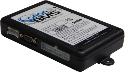
This guide is for the Orion Jr. BMS (plastic unit for 16 cells), pictured below. IIf you have a metal standard Orion BMS unit, click here for troubleshooting steps.
Resolving the issue:
Step 1. Ensure that the BMS has power.
This can be determined by simply looking at the LED on the BMS unit. If the LED is solid red or solid green, the BMS has power and is ready for communication (if the LED is rapidly flashing red, disconnect the cell taps from the BMS immediately). If the LED is not lit, check the CHARGE power (Main I/O pin 4) or READY power pin (Main I/O pin 2) to ensure power is present. Ground must be provided on pin 6. Use a multimeter to check the voltage between the power pin and the ground pin and ensure the voltage is between 9v and 60v. If power is present, and the LED is not lit, the unit may need to be sent to Ewert Energy for evaluation / repair.
Step 2. Ensure that you are using the correct BMS utility.
The Orion Jr. BMS utility must be used to connect to the Orion Jr. BMS unit. Please ensure that you are not inadvertently using the standard Orion BMS utility. The picture of the BMS unit in the utility should match the unit being connected to. If the wrong utility is being used, download the correct utility from <here>.
From this point, there are 2 methods to connect to the Orion Jr. BMS – via CANBUS (CAN-enabled units only) or via the RS-232 serial port. Please select your method below:
Via RS-232
Step 1. Ensure that the serial device shows up in the BMS utility. If the utility says “None Found” for the Selected Adapter, the drivers may not be installed correctly.
Step 2. Select the “List all available serial ports” checkbox, and try each individual serial interface in case the utility was not able to identify which serial port was being used.
Step 3. If using a serial cable to connect to the Orion Jr. BMS, ensure that the cable is actually a straight through cable.
The minimum required pin out can be found in the Orion Jr. BMS wiring manual found here.
Note: A null modem cable will not work, and some cables sold and labeled as “straight through” may not meet the pin out requirements. We recommend using a continuity tester to determine if the cable meets the necessary pin requirements for use with the Orion Jr. BMS. For best results, connect a USB to serial adapter directly to the Orion Jr. BMS unit.
Note: The CANdapter does not function as an RS-232 adapter and cannot be connected to the DB9 on the Orion Jr. BMS.
Note: The Orion Jr. BMS requires the use of the RTS pin in order to provide operating voltage to the serial port. It is possible that some adapters may not provide sufficient power.
Step 4. Try using another USB to serial adapter.
Step 5. Try using another computer.
Via CANBUS
Step 1. Check the unit for compatibility.
Only CAN-enabled Orion Jr. BMS units support a connection via CANBUS (part numbers ORION16C)
Only BMS units with firmware 1.5.0 or newer can connect with the Orion Jr. BMS utility. All CAN-enabled revision C units are capable of CANBUS connections. Revision A and B units shipped with an older version of firmware that does not support connecting to the BMS utility via CANBUS and cannot communicate via CANBUS unless the firmware has been updated.
Please note: Firmware updates, should they be necessary, can only be performed via the RS-232 serial port on the Orion Jr. BMS, regardless of the firmware version or the hardware revision.
Step 2. Ensure the BMS is connected to the PC using the CANdapter by Ewert Energy Systems (only for connecting via CANBUS)
The BMS can only be connected to the computer using the Ewert Energy Systems CANdapter. Other CAN to USB adapters are not compatible. The CANdapter can be purchased here.
Step 3. Ensure that CANdapter and hardware driver are operating correctly.
If the “Connect to BMS” dialog says “None Found,” check the following (otherwise skip to step 5).
1) The CANdapter might not be connected to the computer via USB. To make sure that the CANdapter is connected, disconnect it and then plug it back in and look for three rapid flashes of both the red and green CANdapter lights. If the lights do not flash, try using a different USB port or cable. If the problem cannot be resolved, try using a different computer. If the LEDs still do not flash when the CANdapter USB port is connected, even after using a different cable and computer, there may be a problem with the CANdapter.
2) The CANdapter driver may not be installed or may not be working correctly. Most computers will come with the driver pre-loaded, but some need the driver manually installed. The driver can be downloaded from http://www.ewertenergy.com/products/candapter/downloads/candapter_driver.exe.
Step 4. Ensure that you are connecting the correct pins to the CANdapter and to the Orion Jr. BMS. The CANdapter uses pins 3 and 5, which differs from some other CAN to USB adapters. CAN High (pin 3 on the CANdapter) must be wired into pin 20 on the Orion Jr. BMS. CAN Low (CANdapter pin 5) must be wired into pin 19 on the Orion Jr. BMS. Ensure that the CANdapter is not connected into the DB-9 connector on the BMS, as this port is for use only with the RS-232 serial interface.
Step 5. Verify the correct baud rates.
The Orion Jr. BMS and CANdapter can operate at 125kBps, 250kBps, 500kBps or 1000kBps. The BMS units are shipped operating at 500Kbps by default. However, the baud rate setting on the BMS can be changed. The baud rate of the CANdapter and the BMS must match for successful communication. Important: All devices on a CANBUS MUST communicate at the same baud rate. If any device(s) on the CANBUS communicate at different speeds, the bus will become garbled and completely unusable for all devices on the bus. It may be useful to attempt to connect to the Orion Jr. BMS unit at all the different baud rate settings in the event that the baud rate is set differently than expected. If it is necessary to change the baud rate of the Orion Jr. BMS unit, it will need to be disconnected from other CANBUS nodes and programmed directly. Note: After baud rates are changed in the settings, the Orion Jr. BMS must be power cycled for the new baud rate to take effect (the same can be accomplished by connecting to the BMS and selecting File → Restart BMS in the Orion Jr. BMS utility).
Step 6. When trying to connect to the Orion BMS, check the status of the LEDs on the CANdapter.
If the CANdapter’s red LED comes on and stays on when trying to connect, there are errors present on the CANBUS which can indicate CAN high and CAN low are backwards, the bus is shorted, there are devices operating at different CAN frequencies, there is improper termination, a node on the CANBUS has malfunctioned, or that there are other wiring problems. If the CANdapter LEDs don’t come on, verify that the CANdapter is properly connected. The green and red LEDs should flash a few times when the CANdapter is first connected.
Step 7. Ensure proper wiring of the CANBUS, including proper termination of the bus.
Many problems with CAN communication turn out to be wiring issues on the CANBUS, many of which visually appear to be correct.
First, check for proper termination. The CANBUS will not operate correctly unless exactly two (2) 120 ohm resistors are installed at the 2 physical ends of the CANBUS (one of which is located physically inside the Orion Jr. BMS, unless the Orion Jr. BMS was special ordered without this termination resistor installed). To test for proper termination, completely remove all power from all devices on the CANBUS and measure the resistance between CAN High and CAN Low. It should read 60 ohms (Two 120 ohm resistors in parallel will result in 60 ohms of total resistance). If the resistance readings are not 60 ohms, something is wrong with the termination. A value lower than 60 may indicate that there are too many termination resistors. A value of 120 ohms indicates only one termination resistor is present.
Note: The Orion Jr. BMS ships standard with a termination resistor on the CAN interface. The unit can be special ordered with different configurations.
Important: Exactly one CAN 120 ohm termination resistor MUST be at each physical end of the bus to work properly (total of two resistors)! We receive many inquiries from customers who assume it will work properly without resistors, work with only one or work with the resistors in a different physical location and find that they are unable to communicate with the BMS or find that it only works intermittently. If you have the incorrect number of termination resistors, please add proper termination before inquiring for help, as this solves a large number of communication issues.
The physical layout of a CANBUS matters significantly as this is a high speed communication bus. Wire must be twisted pair cable, with no sections larger than about 1 inch (2cm) of untwisted cable (shielded twisted pair is preferred). Wires must be firmly connected (do not press wires together or use breadboards or phone blocks). Ensure that taps off the main trunk of the bus are kept to 2 feet or less (see the wiring manual for more information about CANBUS wiring). Do not connect CANBUS nodes in a star configuration. Note that simply because there is continuity between the pins does not guarantee that the cable is of sufficient quality for high speed communication.
More tips for locating and resolving CANBUS wiring problems can be found <here>. It may be helpful to create a wiring harness with only CANBUS and power for the BMS to help in diagnosing communication issues.
Step 7. Remove all other devices from the CANBUS and attempt to communicate only with the Orion Jr. BMS.
Some other devices which poll data from the BMS over OBD-II, such as smartphone apps like Torque or other scan tools, can interfere with the BMS’s communication with the utility. Deactivate or remove any device on the CANBUS that might poll data via OBD-II while connecting to the BMS. If removing any devices, ensure that the CAN termination resistors are still in the proper locations as removing a device can alter the termination locations (see step 7).
Step 8. Restart the BMS utility program, power cycle the BMS, and try again in case something had locked up.
Step 9. Attempt to use the RS-232 serial interface.
It is possible that the CANBUS interface may have an issue or may have been damaged. If this is the case, it is sometimes useful to attempt to connect to the RS-232 interface to program the unit.
If all steps above have failed, there may be an issue with the BMS unit. Ewert Energy can test the unit or make repairs if necessary.
![]() Copyright (C) 2019 Ewert Energy Systems
Copyright (C) 2019 Ewert Energy Systems