CANBUS is a high speed network which requires high quality wiring in order to operate properly. As such, it is sensitive to improper wiring. The majority of CANBUS communication problems are caused by poor wiring, incorrect termination, or the use of multiple frequencies on the same bus. Below are some tips for diagnosing CANBUS communication problems:
- There must be exactly two (2) termination resistors of 120 ohms each at the physical ends of the CANBUS. These resistors may be external to the device, but some devices such as the Orion 2 BMS standard (CAN1 only) or Orion Jr 2 BMS have termination resistors installed inside the device (may be special ordered without). Correct termination resistance can be verified by measuring the resistance between CAN-High and CAN-Low with a multimeter. In order to do this, it is essential that all devices on the network are completely unpowered (this will not work reliably if any device on the network has power as it will distort the readings). It should read approximately 60 Ohms (+/- 2 Ohms). There must be exactly 2 termination resistors (120 Ohms each) on the network. Always use termination resistors. Even if the network appears to operate without termination resistors in quiet environments, it may not operate correctly when noise is introduced!
NOTE: Some Orion products have termination resistors built-in inside them
- Both termination resistors must be on the physical ends of the CANBUS (ends of the main trunk). If they are not at the physical ends of the network, then the effectiveness of the termination filtering resistors will be negated.
- All CANBUS wire must be twisted pair cable, even short lengths (longer than 1 inch / 2 cm). The twisted pair wire is an essential part of how the differential mode filtering works on CANBUS, and without it, the signal can be easily distorted. If any external printed circuitboards are used for junctions or bridging connections (not recommended if avoidable), these leads should be as short as possible to minimize interference potential.
- Physical junctions for CANBUS connections should be confirmed to be solid and reliable (and vibration resistant if being used in mobile applications). Friction connections should be avoided. Screw terminal junctions can result in unprotected signal areas that may be more vulnerable to noise or interference.
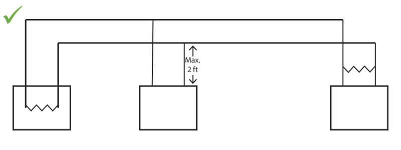
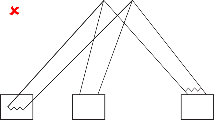
- The network must be shaped like a tree. The main length of the CANBUS is like the trunk of the tree and there can be small branches that come off the main trunk. The maximum length of the trunk and branches depends on the baud-rate running, but is typically limited to no more than 2 feet (0.6 meters)
- CAN-High and CAN-Low wires must be the same length. Differences in length between CAN-High and CAN-Low wires can cause distortion due to common mode filtering.
- Depending on the CANBUS baud-rate, maximum bus trunk length (total distance between the two physical ends of the network) requirements may apply that are listed below. NOTE: These are to be considered absolute maximum lengths. Signal degradation may occur at shorter distances depending on outside factors.
Maximum Main Trunk Length:
125 Kbps: 500 meters
250 Kbps: 250 meters
500 Kbps: 100 meters
1000 Kbps: 25 meters - Ensure that CAN-High and CAN-Low are connected in the correct order. If CAN-High and CAN-Low are backwards on any device on the network, it will obliterate or severely distort traffic and make communication impossible.
- Ensure CAN-High and CAN-Low are not shorted together or shorted to ground or V+. Test to make sure there is no electrical conductivity between CAN-High and ground or CAN-Low and ground (this can happen if one of the wires gets shorted to the shield or gets pinched or sliced by a metal enclosure).
- All devices on the CANBUS network must be running the same baud-rate. If there are devices running multiple different baud-rates then this may obliterate all CANBUS traffic. If the baud rate on an Orion BMS product must be changed, disconnect the device from the network, and update the baud rate with just the BMS product and the CANdapter connected. If the baud rate is changed on an Orion BMS product, the Orion BMS product must be power cycled for the new baud rate to take effect.
- All devices on the network must share the same ground. Different ground potentials between devices will lead to common mode voltages forming on the CANBUS. These will distort communication signals and can lead to damaged equipment and may also pose a safety hazard. If the same grounds cannot be used, an external CANBUS isolator may be required to provide galvanic isolation to disrupt ground loops.
- If the CANBUS wire being used is a shielded cable, the shield should be grounded on one end only. If both ends of the CANBUS wire shield are grounded then ground loops may be formed which can cause interference.
- Ensure that all CANBUS wiring is solidly connected. CANBUS wire junctions must be soldered together or securely spliced. Junctions may NOT simply be twisted together or held together with wire nuts or friction. Do not use terminal blocks, phone cable junction blocks, or other signal processing blocks. These can distort CANBUS communication signals.
- When stripping the CANBUS wires back, it can be easy to accidentally pierce the insulation of the CAN-High or CAN-Low wires. Inspect any joint or section of wire where the outer CANBUS sleeve has been stripped back to ensure that the CAN wires were not inadvertently damaged as well.
- Whenever possible, route CANBUS wires away from noisy circuits. Do not twist CANBUS wires with other wires.
- If using the CANdapter (produced by Ewert Energy Systems), please ensure that you are connecting the correct pins to it. The CANdapter uses pins 3 and 5, which differs from some other CANBUS to USB adapters. Pin 3 is CAN-High, pin 5 is CAN-Low, as shown below. It is very easy to get these pins reversed by mistake, take care in ensuring they are correct.
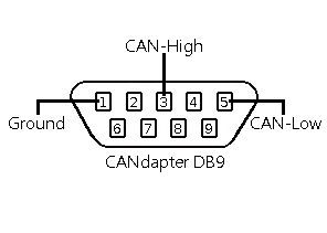
Diagram above is from perspective of wires coming towards the viewer from the female end of the connector. See CANdapter manual for more details.
![]() AN2657 - Copyright (C) 2019 Ewert Energy Systems
AN2657 - Copyright (C) 2019 Ewert Energy Systems