Disclaimer: The following information is provided as a guide for integrating the Orion BMS with the PFC series chargers by Manzanita Micro. While the information here is believed to be correct, it is the user’s responsibility to verify all aspects of the end application and the suitability of the following. Ewert Energy has no affiliation with Manzanita Micro and provides this information for informational purposes only and is not responsible for changes in specifications made by Manzanita Micro. Consult the full user manuals for both products for more information. “PFC-20”, “REG BUS” are trademarks or product names belonging to Manzanita Micro.
Charger Overview:
CAN Communication: No
Current limiting via 5V analog signal: No
Field programmable maximum voltage: Yes
The PFC chargers by Manzanita Micro are designed to be able to connect with distributed style bypass regulators via the REGBUS. The charger looks for a shutdown signal on the REGBUS to either put the charger into a constant current mode (used for bypass balancing with their proprietary regulator boards) or to simply turn off the charger when the shutdown signal is received. When receiving the shutdown signal, the behavior of the charger depends on the position of the dip switches. ****DIP switches 1 – 3 must be OFF for the charger to turn off immediately as soon as the shutdown signal is received, otherwise the charger will continue to charge at a set current for a period of time after the signal has been received, overcharging the batteries. ****. See the manual for instructions on setting dip switches.
The shutdown signal is received by the charger when pins 1 and 2 on the RJ-25 connector are shorted together. If pins 1 and 2 are open (not connected together), the charger will be active. When pins 1 and 2 are shorted, the charger becomes inactive. As such, the shutdown signal on the REGBUS connector can be used as a simple method to turn on and off the charger using the charger safety or charge enable signal from the Orion BMS, however the input is not failsafe and therefore proper precautions must be taken.
The pinout for a RJ25 connector can be found here:
http://en.wikipedia.org/wiki/F
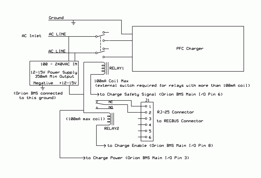
The schematic in figure 1 shows a configuration where the Orion BMS is connected to the shutdown signal on the REGBUS using a simple normally closed relay. The open drain charge enable signal from the Orion BMS goes low when charging is enabled to activate the normally closed relay. When the relay is active, pins 1 and 2 on the reg bus connector are opened and the charger is allowed to charge. When the charge enable signal from the Orion BMS is inactive (floating), the relay is inactive and pins 1 and 2 on the REGBUS connector are shorted, shutting off the charger. While the relay is configured to be failsafe (meaning if the BMS were not powered, the charger would not engage), if the REGBUS connector were to become disconnected from the charger, the charger would default to being on rather than off. Additionally, there have been reports of the charger continuing to charge even though the REGBUS shutdown signal was sent. Because of these things, it is very strongly recommended that a backup ‘charge safety’ relay be used in series with the AC power to the charger. Because relays can fail, it is recommended that both control methods are used. The AC relay acts as a backup method for the BMS to disable the charger and also provides a default behavior of having the charger off.
When selecting a relay, it is important that both AC lines are interrupted to the charger together since the PFC chargers are designed to operate with split phase power sources (2 hot AC lines or 1 hot and 1 neutral.) Because of this, a 2 pole relay must be used to interrupt both AC input lines at the same time. The relay must be minimally rated for the maximum possible current, however we strongly recommend selecting a relay with a higher rating than the expected maximum current for added reliability. For example, if the maximum current drawn by the charger is 20 amps, a 30 amp relay (or higher) should be considered. Additionally, if the charger could possibly be powered by DC rather than AC, the relay MUST be rated for DC current since AC and DC currents behave very differently and a relay designed to interrupt AC current may not interrupt DC current.
In addition to providing the method for the BMS to turn off the charger, the maximum voltage on the charger should be configured to the maximum pack voltage. This is done such that if for whatever reason the BMS were unable to turn off the charger that the charger would turn itself off when the maximum voltage of the pack was reached. This greatly reduces the risk of thermal runaway or significant damage to the battery pack. Instructions for setting the maximum charging voltage are available in the user manual.
As always, when integrating with any charger, it is important to monitor the first few charge cycles to ensure that the BMS is able to turn off the charger and that it is programmed with the correct maximum cell voltage. Tests should be performed to ensure that the default mode of the charger is off. This can be done by either disconnecting the main I/O connector from the BMS and ensuring that the charger turns off or by intentionally causing a serious error code on the BMS by unplugging the total voltage tap connector and ensuring that the charger disengages (errors on the BMS must be reset before normal operation will resume.) Additionally, the system should be manually monitored during the first full cycle or two to ensure that the charger turns off at the right time.
![]() AN1 - Copyright (C) 2019 Ewert Energy Systems
AN1 - Copyright (C) 2019 Ewert Energy Systems

 AN1
AN1


