Disclaimer: The following information is provided as a guide for integrating the Orion BMS with the Valeo chargers. While the information here is believed to be correct, it is the user’s responsibility to verify all aspects of the end application and the suitability of the following. Ewert Energy has no affiliation with Valeo / Siemens and provides this information for informational purposes only and is not responsible for changes in specifications made by the manufacturer. Consult the full user manuals for both products for more information.
The Valeo chargers must be controlled via the CANbus interface to operate. At the time this document was written, Valeo offers a single 3.5 kW sealed charger that operates between 180vDC and 430vDC output with integrated liquid cooling and universal AC input.
IMPORTANT NOTE: Valeo chargers utilize liquid cooling in order to operate. This is REQUIRED and must be used whenever the charger is active. Failure to supply proper liquid cooling to the charger may damage the charger and void the factory warranty. Please see the Valeo documentation for details.
Ordering the charger
While the Valeo charger does have integrated support for SAE J1772 operation, there are incompatibilities between it and the version of the standard used in the United States. For this reason, the charger should be ordered with the “SW1” software loaded. This means that the charger itself is not expecting the J1772 input pins to operate. The charger can still be used with J1772 charging stations. To do this, please use the Orion BMS 2 which has native support for J1772 integration and control. More details on how to connect the BMS to control J1772 EVSE stations is available in the Orion BMS 2 wiring manual.
IMPORTANT NOTE: At the time this document was written, the manufacturer does not permit multiple chargers to be installed together in parallel. Please inquire with the battery charger supplier for more details on this restriction if parallel operation is required to see if any solutions exist.
Interfacing with the charger
Interfacing the Valeo charger to the Orion BMS is primarily done through the CANBUS. An optional analog safety shutoff can be added if desired. The following diagram shows the standard configuration.
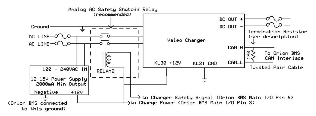
In this diagram, the CAN connection on the Valeo charger is connected to either the CAN1 or CAN2 interface on the Orion BMS. A CANBUS requires exactly two 120 ohm termination resistors at the physical ends of the BUS. Unless the Orion BMS was special ordered with a different configuration, the Orion BMS has an internal termination resistor on the CAN1 interface and no termination resistor on the CAN2 interface. At the time of this writing, the Valeo charger does not have an internal termination resistor. Please see the wiring manual for more information about proper termination of the CAN bus and for wire length limits for CAN nodes. The Valeo charger may be connected to either of the CAN interfaces on the Orion BMS (CAN1 or CAN2.) The Valeo charger comes configured by default to operate at the 500kBps baud rate. Either CAN interface on the Orion BMS can be changed to operate at different baud rates baud rate. All devices on a CAN bus must operate at the same frequency, so if the BMS is integrating with other devices requiring a different frequency, it may be necessary to put the Valeo charger on one of the CAN interfaces and the other devices on the other interface to accommodate both frequencies.
The pinout for the input / output harness on the charger is as follows:
- [Pin 4A] Light Green (22 Gauge) – CAN High
- [Pin 4B] Tan (22 Gauge)- CAN Low
- [Pin 4G] Tan (16 AWG) – KL31 Ground
- [Pin 1H] Brown (16 AWG) – KL30 +12v
Please note that the exact colors of the above wires may be different than the harness received.
NOTE: While other pins may be present on the harness, only the above-listed pins are necessary for interfacing with the Orion BMS.
In addition to the CANBUS communication lines, the +12v KL30 and Ground KL31 lines MUST be connected. This is what provides power to the charger to operate its onboard logic circuitry. If they are not connected then the charger will not operate. The typical current draw on the +12v KL30 input line is between 300mA and 650mA continuous while the charger is operating. The +12v input line can be powered off the same power source that is connected to Charge Power on the Orion BMS. The installer must make sure that the power supply for this power source is sufficient to handle both loads (2 Amp minimum is recommended).
NOTE: The Valeo charger will continuously draw approximately 600mA from the 12v input source during the charging process (regardless of whether charging has completed or not). Unless the onboard vehicle 12v battery is being continuously topped off by a DC/DC converter or another charging method, an external 12v power supply (derived from the AC mains that the charger is connected to) is strongly suggested in order to avoid draining the onboard vehicle auxiliary battery.
It is strongly recommended that an analog (secondary) shutoff for the charger be provided by adding an AC relay. The charger is primarily controlled using the CAN interface. While CAN is itself a robust protocol, it is still a digital protocol which can be susceptible to errors and bus lockups. An analog backup can turn off the charger even if communication errors are present on the CAN bus such that the batteries are always kept in a safe state. The only method of analog backup for this version of the charger is interrupting the AC power to the charger.
Because the Valeo chargers can be used on split phase connections (standard residential 240V AC), both AC “hots” must be interrupted using a double pole relay. The relay coil must be less than 175mA for the original Orion BMS (older model with black enclosure), or less than 500mA when used with the Orion 2 BMS (newer model with silver enclosure). We recommend over-sizing the relay to ensure it can properly handle the AC current. It is up to the user to verify that the relay used is a suitable relay for the application and that the relay meets any necessary specifications.
The Orion BMS utility has built-in support for the Valeo charger CAN protocol.
Steps for configuring the Orion BMS to communicate with the Valeo Charger:
1.) Open the Orion BMS software utility and load the appropriate profile into the editor by either downloading the existing settings from the Orion BMS (“Recieve Current Profile From BMS”) or by opening a profile previously saved to disk.
2.) On the “Battery Profile” tab, select the “CANBUS Settings” tab and select the Checkbox next to “Valeo Charger” in the dialog at the bottom. Enabling this checkbox will popup a dialog that explains changes made to the profile and asks for confirmation. Click OK after reading.
3.) Manually ensure the proper baud rate for the CAN interface connected to the Valeo charger. This can be verified on the “CANBUS Settings” tab and select the proper baud-rate for the CANBUS interface that the Valeo Charger is connected to (usually 500kBps.) Note: If changing the baud rate, ensure that all devices on the selected CANBUS interface operate at the same speed. CANBUS baud rate changes only take effect when the BMS is reset or power cycled. If the baud rate is changed for the interface connected to the CANdapter, the baud rate will need to be changed when attempting to connect to the Orion BMS after it is reset.
4.) After verifying all profile settings, upload the new changed settings to the BMS.
The Valeo charger setup should be thoroughly tested before being left alone to ensure that the CANBUS control is working properly.
Valeo Specific Troubleshooting:
If the charger does not charge when connected to the Orion BMS:
- Ensure that the BMS is calling for charge. Connect to the Orion BMS using the BMS utility and monitor the charge current limit (CCL) to ensure that the BMS is allowing charge. Certain error codes on the BMS will prohibit charging! If error codes are present, look up the codes in the troubleshooting guide to troubleshoot these first. The troubleshooting guide is available on the Downloads Page.
- Ensure that the BMS is able to communicate with the charger via CANBUS. With the CANdapter connected to the same CAN interface as the Valeo charger, open the Orion BMS utility, select the “3rd Party Data” tab at the top. Select the Valeo Charger from the drop down menu and click “Connect to device”. If the CANBUS is operating correctly, data will show up from the charger such as AC voltage. If this data is not present, the charger is either off or there may be a CAN wiring issue preventing the charger from communicating.
Please see the troubleshooting guide for more information which is available on the Downloads Page.
Important: After making any changes to the charger configuration it is very important to test the setup while closely monitoring the battery pack to ensure that the charger turns off properly at the correct time.
![]() AN2823 - Copyright (C) 2019 Ewert Energy Systems
AN2823 - Copyright (C) 2019 Ewert Energy Systems