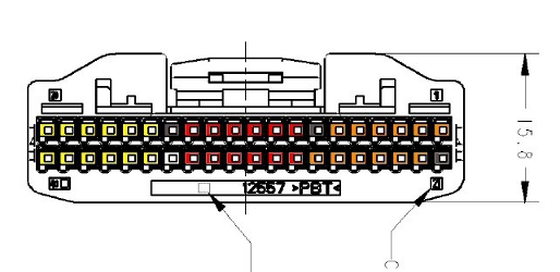
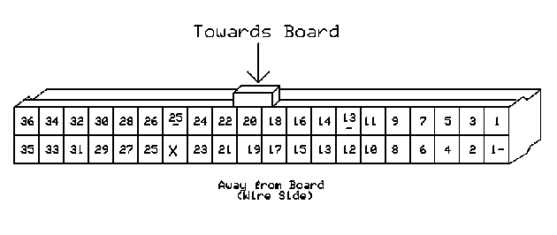
Note: Perspective is from back of connector with wires coming out towards the viewer.
Note: This diagram is intended to be used for quick reference only. Please consult the BMS wiring manual for details on the pinout and wiring instructions.
| < Main I/O Harness Diagram | CANdapter DB9 Diagram > |