Disclaimer: The following information is provided as a guide for integrating the Orion BMS with the Elcon and TC chargers. While the information here is believed to be correct, it is the user’s responsibility to verify all aspects of the end application and the suitability of the following. Ewert Energy has no affiliation with Elcon or TC chargers and provides this information for informational purposes only and is not responsible for changes in specifications made by the manufacture. Consult the full user manuals for both products for more information.
The TC / Elcon chargers can be controlled either via an on/off signal, a CANbus interface or via a 2-5V analog input. The charger is programmed from the factory to support one of these three control methods. Any charger can be returned to the factory for re-programming to support CAN.
Ordering the charger
When ordering the Elcon charger, we recommend selecting a charge algorithm which is as close to constant current as possible which terminates at a voltage slightly higher than the maximum possible pack voltage. While the algorithm is not relied on for normal operation, it serves as an additional backup to prevent the pack from becoming severely overcharged in the event of a wiring failure or other failure.
NOTE: The above recommendation only applies to NON-CANBUS Elcon chargers. The CANBUS version of the Elcon chargers cannot be ordered with any algorithms (the CAN version of the charger is completely controlled by the BMS via CANBUS and does not use any internal algorithms).
Interfacing with the standard version
For most applications, it is desirable for reasons of extending the battery’s lifespan to charge only to 90-95% state of charge. Unless the battery is being charged at high C rates (the rate of charge verses the amp hour rating of the cells), it should be possible to achieve this simply by using the charger in a constant current mode using the enable and disable switch. For this configuration, the following diagram shows the simplest connection:

In this setup, the Elcon charger is disabled by default in the event that the BMS is disconnected or fails (fail safe.) When AC power is present, the 12-15V power supply is energized and supplies power to the Orion BMS’s CHARGE power supply input. When the BMS detects power at the CHARGE power supply input, it does self checks and tests the battery to ensure it is capable of receiving a charge. When the BMS determines that it is ready to accept a charge, it pulls the charger safety signal to ground turning on RELAY2 in the above diagram. When RELAY2 is energized, the Elcon charger is enabled and begins to charge the battery pack. When the BMS determines that the battery is full or can no longer accept a charge, the BMS shuts off the charger safety signal which then floats high and shuts off RELAY2, turning off the charger.
Notes about the above schematic:
- The external 12-15V power supply should supply a voltage equal to or higher than the always on power supply for the BMS if it is desirable for the BMS to draw operating current from the AC power supply. Due to the wide operating voltage of the Elcon, a switching mode power supply should be used to that accepts universal voltages from 100-250VAC to match the AC input for the Elcon charger.
- On Elcon PFC models, the +12V supply from the Elcon charger cannot be used to power the BMS as it is rated at only 50mA. Applying a load higher than 50mA may damage the charger. Newer UHF (1.8kW, 3.3kW and 6.6kW) models now come equipped with a 5A output that is specifically designed for powering the BMS.
- The BMS has internal protection to protect against back EMF from the relay coil, though an additional clamp diode can be added if desired for additional protection
- On the original Orion BMS, the charger safety signal has a maximum load of 175mA. A relay with a coil current less than 175mA must be used in this application or an amplification circuit must be used (see the wiring manual for more details). The newer Orion 2 BMS can power relays up to 500mA continuous.
- An appropriate opto-isolator or solid state relay may be used instead of a standard mechanical relay. If either are used, care must be taken to ensure that leakage current is below the threshold for turning the charger on and a pulldown resistor may be required on the charger’s enable line. (see the wiring manual for examples of opto-isolators connected to the open drain outputs.
In addition to the BMS connection, we strongly recommend setting the Elcon’s maximum charger voltage just above the maximum pack voltage. This way, if there is a problem with wiring or a problem with the BMS, the charger will shutoff before the batteries are severely damaged.
Interfacing with the CAN enabled version
When interfacing the Orion BMS with the CAN enabled version of the Elcon charger, we recommend also proving an analog shutoff for the charger. While CAN is itself a robust protocol, it is still a digital protocol which can be susceptible to errors and bus lockups. An analog backup can turn off the charger even if communication errors are present on the CAN bus such that the batteries are kept in a safe state. The only method of analog backup for this version of the charger is interrupting the AC power to the charger (the enable pin on the DIN connector cannot be used to shutdown the charger when configured for CAN.)
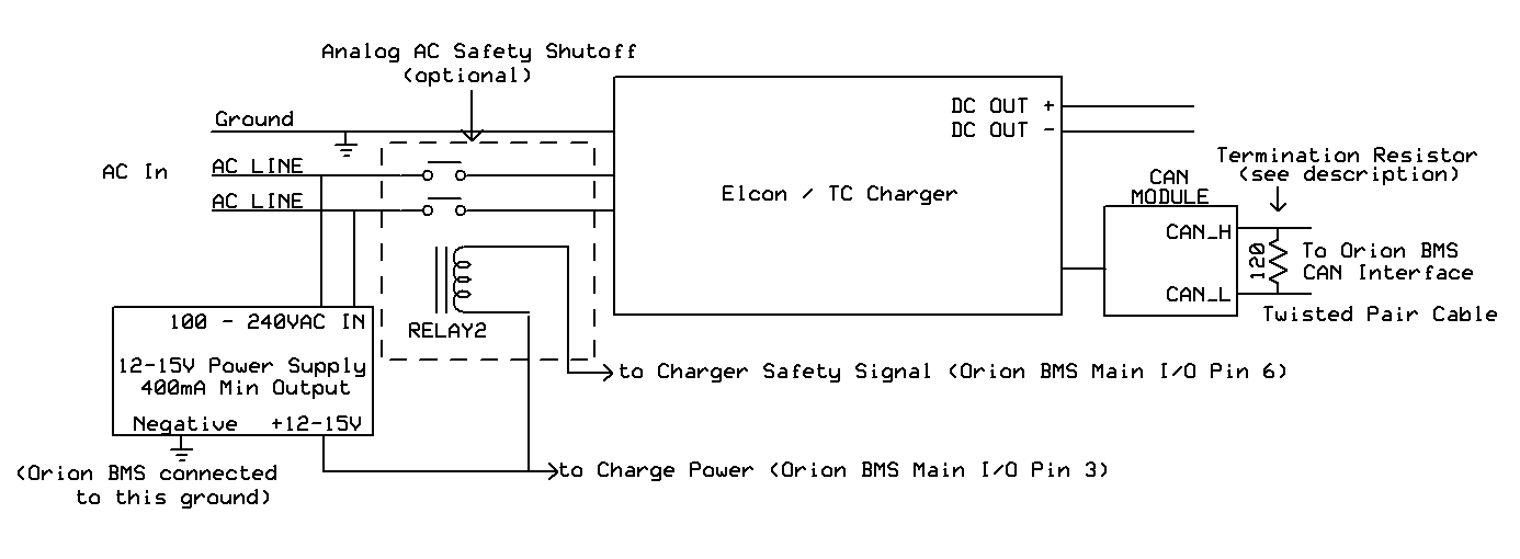
Please see the first method for a description of how the above circuit works. This circuit works the same way as the first example, however in the CAN version of the charger, the charger is primarily controlled using the CAN interface. An optional relay (RELAY2) on the AC power source to the charger serves as a backup to ensure the charger can be shutoff in all situations. Because the Elcon chargers can be used on split phase connections (standard residential 240V AC), both AC “hots” must be interrupted using a double pole relay. The relay coil must be less than 175mA for the original Orion BMS or 500mA for the Orion 2 BMS. We recommend over sizing the relay to ensure it can properly handle the AC current (for example, for a 15A AC current, we recommend using a 20A relay or larger.)
The CAN module for the Elcon charger at the time of this writing does not include a termination resistor. A CANBUS requires exactly two 120 ohm termination resistors at the physical ends of the BUS. Unless the Orion BMS was special ordered with a different configuration, the Orion BMS has an internal termination resistor on the CAN1 interface and no termination resistor on the CAN2 interface. Please see the wiring manual for more information about proper termination of the CAN bus and for wire length limits for CAN nodes. The Elcon charger may be connected to either of the CAN interfaces on the Orion BMS (CAN1 or CAN2.) The Elcon charger is hard-coded to operate at the 250kBps baud rate and both interfaces on the Orion BMS can be changed to a 250kBps baud rate. All devices on a CAN bus must operate at the same frequency, so if the BMS is integrating with other devices requiring a different frequency, it may be necessary to put the Elcon charger on one of the CAN interfaces and the other devices on the other interface to accommodate both frequencies.
In addition to the BMS connection, we strongly recommend setting the maximum charger voltage just above the maximum pack voltage. This way, if there is a problem with wiring or a problem with the BMS, the charger will shutoff before the batteries are severely damaged. This option is specified at the time that the charger is ordered.
The Orion BMS utility has built in support for the TC / Elcon charger CAN protocol.
Steps for setting up the CAN for the Elcon / TC Chargers:
1.) Open the Orion BMS software utility and load the appropriate profile into the editor by either downloading the existing settings from the Orion BMS (“Recieve Current Profile From BMS”) or by opening a profile previously saved to disk.
2.) On the “Battery Profile” tab, select the “3rd Party Devices” tab and select the Checkbox next to “Elcon / Bestgo / TC Charger”. This will popup a dialog that explains changes made to the profile. Click OK after reading.
3.) Manually ensure the proper baud rate for the CAN interface connected to the Elcon charger. This can be verified on the “Communications Settings” tab and select “250 Kbps” baud-rate for the CANBUS interface that the Elcon / TC Charger is connected to. Note: If changing the baud rate, ensure that all devices on the selected CANBUS interface operate at the same speed. CANBUS baud rate changes only take effect when the BMS is reset or power cycled. If the baud rate is changed for the interface connected to the CANdapter, the baud rate will need to be changed when attempting to connect to the Orion BMS after it is reset.
4.) After verifying all profile settings, upload the new changed settings to the BMS.
The Elcon / TC charger setup should be thoroughly tested before being left alone to ensure that the CANBUS control is working properly.
Note: CAN Modules for the Elcon chargers manufactured prior to Jul 2011 may lock up if a high frequency of CAN messages are present on the attached CAN interface. We recommend contacting your Elcon distributor to purchase upgraded equipment. If an older CAN module is used, the recommended backup relay on the AC input must be installed (see above diagram.)
Analog current limiting method:
NOTE: The pins on the DIN connector of the Elcon charger are not electrically isolated from the high voltage battery pack and a direct connection between the BMS and the charger is not recommended!
NOTE: This method requires the “2-5v Current Limit” functionality to be factory programmed into the charger (ie: it must be enabled by the charger manufacturer at time of purchasing the charger). This feature MAY NOT be available on the charger by default.
Ewert Energy does not have a recommended procedure for interfacing with the 2-5V analog input on the Elcon chargers at this time. Please consider the CAN enabled version of the Elcon charger if current limiting functionality is needed.
Troubleshooting:
If the charger appears to stop charging prematurely, we recommend connecting to the Orion BMS unit using the BMS utility and monitoring the charge current limit (CCL) to determine if the BMS is restricting the current. If the CCL is zero, the BMS is turning the charger off for one reason or another. If the CCL is not zero, the charger may be defective or there may be a wiring problem. Please see the troubleshooting guide for more information which is available on the Downloads Page.
Important: After making any changes to the charger configuration it is very important to test the setup while closely monitoring the battery pack to ensure that the charger turns off properly at the correct time.
![]() AN1172 - Copyright (C) 2019 Ewert Energy Systems
AN1172 - Copyright (C) 2019 Ewert Energy Systems